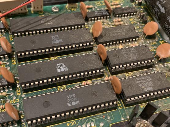
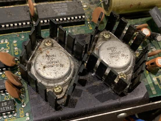
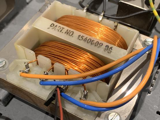
Had a look into another one of @eazy‘s patients. I think it might „just work“, but it is in dire need of some cleaning. Plus the usual tantalums should be replaced. It might also get the spiffy low noise regulator upgrade… let’s see.
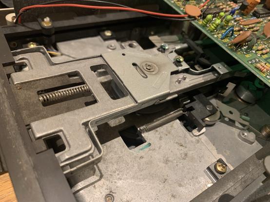
It’s a 1984 short board with ALPS mechanism. So I have high hopes it will work.
#commodore #c64 #retrocomputing
Oh it seems we hit jackpot here! This drive comes with a 6502C. This is rated for up to 4 MHz! Not sure where I could use this, but good to know I have one of those!
It’s very hard to find information on this variant. Most hits refer to the 6502c, codename Sally, which MOS produced for Atari‘s home computers. But that’s a different thing with slightly different pinout. So were there ever any 4MHz machines? I have a bunch of 6502A which can be used e.g. in the 264 machines such as the C16 and 264 (with adapters). They were I think rated up to 2 or 3 MHz.
Very interesting transformer on this one. It is missing the usual insulating tape. I guess it is not strictly necessary. But it also shows the thin wire on the primary, and the much chunkier windings on the secondary side.
#retrocomputing #commodore #c1541
The drive mechanism is an ALPS FDM2111-B5. The ALPS drives are usually very reliable. Simple and good to maintain. This one has a weird motor driver board, with a SIP Sony IC. I hope the RPMs are still fine, because I don't have a replacement for that!
I have cleaned the PCB and the drive. All looks very pretty now. And the drive seems to work.
Head assembly got cleaned and lubricated. RPMs are a tad low, but alignment is still good. Should function just fine.
There is just one literal catch: the floppy catches on the upper spindle when inserting. This seems to be a mechanical problem. When you push down on the top lever it gets in fine. I guess the thing got slightly out of shape at some point.
In the closed latch position I VERY carefully bent the front part of the lever mechanism up, and now the disk slides in much more easily.
Demo time! The drive seems to be working just fine. It plays Matrix 2 without a glitch. Just some cleaning, lubrication and slight bending.
Just one more thing: should I mod the drive to use the modern switching regulators? Right now it is running relatively warm, and I am not sure if this particular transformer can be modded for 240V.
Yes, do the mod!
77.3%
No, leave it original!
13.6%
Try to 240V mod it!
9.1%
Poll ended at .
...and the drive is dead. It just died. Motor spins, no LEDs. This is usually indicative of a broken 5V rail. A quick check shows that the 7805 is outputting 0V, it's input voltage is about 3V. Way too low. Desoldering CR1 shows that this is not a FULL BRIDGE RECTIFIER anymore, but rather a HALF BRIDGE RECTIFIER...
The disks still don’t want to slide in correctly. They think this thing got bent at some point pretty badly. Either way I cut up some self adhesive rubber feet and stuck them up at the front cover so the lever mechanism rests on it when the latch is open.
The space between the spindle and the latching mechanism isn’t big to begin with. But without those rubber feet the plastic thing at the top as at an angle, narrowing the gap even further und the disk got stuck.
While determining how this all works I dismantled the cover plate and saw that this drive probably had some moisture or water ingress in the past. There are some dark spots on the aluminium case that are not on my other Alps drive.
Oh, and nobody was correcting me when I was measuring incorrectly! It seems I connected the clips the wrong way around in the second measurement on the bridge rectifier. If I measure correctly it shows that one diode seems to be shorted, instead of open. We get 0.6V+0.6V=1.2V on one half of the rectifier, but only 0.6V on the other! So one of the four diodes is shorted.
Replacement rectifiers arrived. The drive is working again! Case closed.
@root42 you should only be measuring 1.2 between + and -. From + to any AC and from - to any AC should all 4 be like 0.6. If one diode was shorted, you'd be able to measure that short directly (with the test leads connected both ways around).
So the diode on the second photo between + and AC1 is faulty, as it drops too much voltage (and probably even more than 1.2 under load!).
@lasse Ok, let me try to wrap my head around that. I was first thinking with a bridge rectifier I am measuring two diodes ... but I think you are right. from AC to its nearest DC pole it is only one diode. How weird that this diode has 1.2V....
@root42 replace with a GBU and bob's your uncle.
@lasse what's a GBU?

@root42 whoops, meant to say KBU instead. That's a beefy case for rectifiers. GBU's are wide and flat instead.

https://www.reichelt.de/de/de/shop/produkt/brueckengleichrichter_50_v_8_a-9228

Something like this.

NB Brückengleichrichter, 50 V, 8 A | Brückengleichrichter günstig kaufen | reichelt elektronik

Brückengleichrichter, 50 V, 8 A Brückengleichrichter von NB - Schnelle Lieferung ✓ günstige Preise ✓ Für Gewerbe und Privat ✓ Jetzt online bei reichelt elektronik bestellen!

@lasse I ordered some KBP202 now, as they had very similar characteristics as the BR82D. Either way almost any BR should be fine, as the original was only 2A and that seems to be the minimum anyway.
@root42 yes, most anything should be fine. Those KBU are pretty rugged though, and they do fit in this case, both wrt pinout and case size 😎
All right. I actually modded the transformer to 240V already. Now waiting for the replacement bridge rectifier to arrive. Maybe then I will also do a switching regulator mod. But with the 240V mod it should already run cooler.
@root42 It's a tricky thing. With an internal PSU, changing the transformer config to 240V would probably be the best choice. I doubt that the transformer has those taps, though.
The next best thing is the mod on the secondary that deals with the higher AC voltage.
For drives with external power bricks, modern PSUs like the one by Sven Petersen are the best solution, I think.
@VintageProject I just checked -- the third pin on the primary side is exactly that tap. I need to rewire middle pin to the left pin -- looking from the back of the device.
@root42 Well, better triple-check. I don't trust Commodore designs, and I would be cautious to believe that they incorporated a 230V option. :)
Apart from that it seems like the best way to go for future-proofing.
@VintageProject Yes, I measured twice. The third pin seems to increase the number of windings, the resistance goes up.
@root42 @VintageProject you can also measure the AC voltage if powered on
@vogelchr @root42 Yes, that would be the triple-check thing: Disconnect the secondary and measure the transformer output before applying voltage to the more delicate circuitry.
You never know, especially with Commodore.
Or anything IT/computer-related, as far as I'm concerned. 😆

@VintageProject @root42 no, not on the secondary.

Also on the additional taps on the primary one can measure the different ratios, before resoldering connections.

Assume you’re currently feeding 230V into the old nominal “220V” tap, you can check if some other (unlabelled) tap would be the “240V” by measuring there: you’d expect to see 250V or so, if your guess was right. As it also takes winding direction into account, it’s more reliable than just winding resistance.

@vogelchr Good point! Didn't think that would work. Transformers are magic...
@root42 https://en.wikipedia.org/wiki/Autotransformer (German: Spartransformator, it saved on copper :) )
Autotransformer - Wikipedia

@vogelchr @root42 Oh, that's an interesting aspect. I think I'll take that into my troubleshooting/repair book.
Thanks for the explanation!
I didn't think that way.
@root42 my guess: The pivot point between the plastic front lever and the sheet metal worn out. (at the place where you press with your finger. it should be circle and probably now oval shaped.
@adorfer Yes, could also be, the lever pushes against the top part of the front bezel, and it might have worn that out.
@root42 that's interesting. My older 8050 drive has a pot to turn to alter the rpm. Does VR1 do the same on your drive?
@ColinHaynes yes, the motor drive board has the pot, see my other post with the drive pic. 1.5 RPM however is still fine, and I didn’t want to mess it up. Would need to apply new loctite. It might be the drive will change a bit when it is used more.
@root42 the disk latches on the 8050 are a thing of beauty. But it's a bugger that it runs best when fed 96tpi diskettes. Which are not cheap. What does yours use?
@ColinHaynes the 8050? I have two now. I use no name DD diskettes. The BASF 100tpi disks I bought don’t work at all.
But I still need to make both 8050s better. Both have issues on drive 0. Those are very unreliable.

@root42 My 8050 works best with the 3M 96 tpis I bought. It can work with no-name disks, but it's not as reliable.

The 3040 and 4040 I have will work with pretty much any old crap I throw at them...

@ColinHaynes A 4040 would be very nice to have... I think the 8050s are way too much hassle, beautiful as they are...

@root42 I got it as part of a PET (4032)/printer (3022)/disk drive set I bought from a retired chap who used to work at the National Coal Board. There was a box of disks most of which were readable. It was nice to find programs from the 80s that still work.

My fumbling repair threads with much help from others here:

https://www.vintage-radio.net/forum/showthread.php?t=201990

and here:

https://www.vintage-radio.net/forum/showthread.php?t=203300

Commodore PET 4032/8050/3022 - UK Vintage Radio Repair and Restoration Discussion Forum

Commodore PET 4032/8050/3022 Vintage Computers