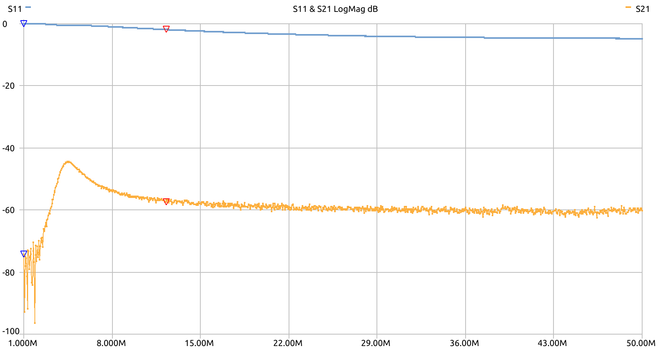
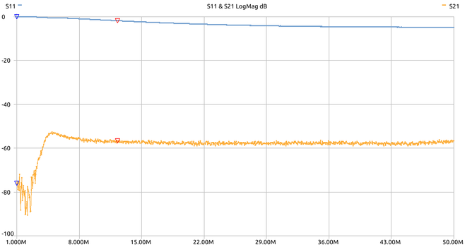
For an auto antenna tuner I'm building, made a directional coupler. It should provide -20dB on forward and reflected outputs. Made a base PCB in #kicad. Primaries, 1 turn, are 0.65mm wire and secondaries are 10 turns 0.38mm. Next to test it out with the nanoVNA and see how close to spec. it is.
So finally got around to measuring the directional coupler. A few lessons first:
1. BNC to banana jack adapters are only good for DC. Thought those could be good for lower bands RF. They're not.
2. Oscilloscope probes do work fine for HF RF. For 10:1 probes, take the attenuation into account.
3. Having trouble with nanoVNA? Getting crashes on nanoVNA-saver? Upgrade the firmware. I didn't upgrade mine since I bought it (in 2019).
Here are directional coupler measured results for both 'Forward' and 'Reflected' coupling. In both cases I get about -60dB attenuation. The Rigol probes I used are -20dB each, so need to add 40dB for the real world number. I get -20dB which is what I was aiming for. Still not clear about the "bump" at ~4.5MHz and the drop before it. As the tuner will be for +8MHz frequencies, I'm not too worried about it.