presenting without elaboration
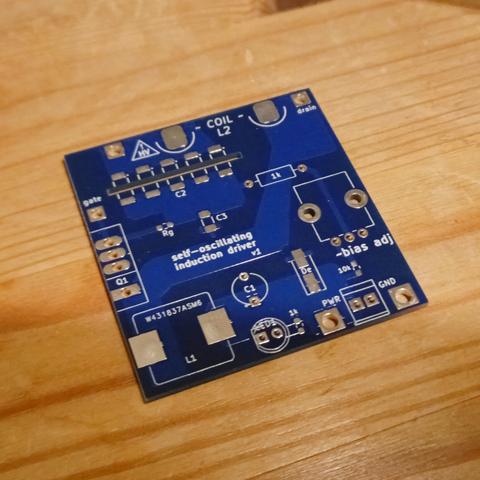
that 1k through-hole resistor is there becaussse it was either have a resistor do double-duty as a jumper wire, or switch to a four-layer board just for one trace.
not a good solution but maybe the least-bad.
update:
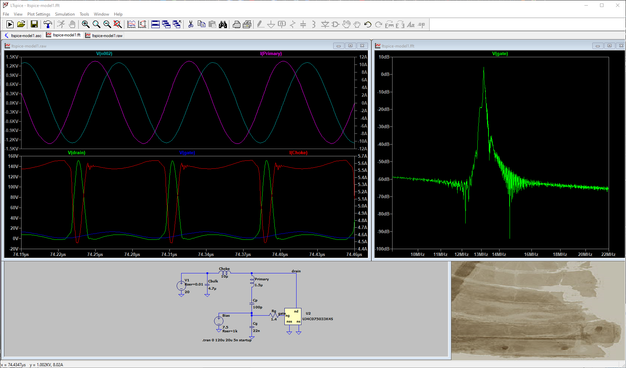
realized wait, LTspice can totally calculate power dissipation; I ought to see if my components are gonna cook.
fine: MOSFET drawing somewhere like 12-15W which is A Lot but I planned for a heatsink.
probably not-fine: >10W on an 1808 capacitor, 400mW on a 0603 resistor
🌶️ ♨️ 😅
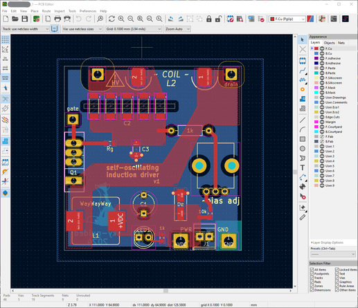
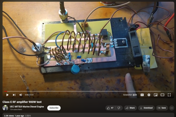
me: i need to think very carefully about this board layout and I want things to be clean as possible.
other folks, with apparent success:
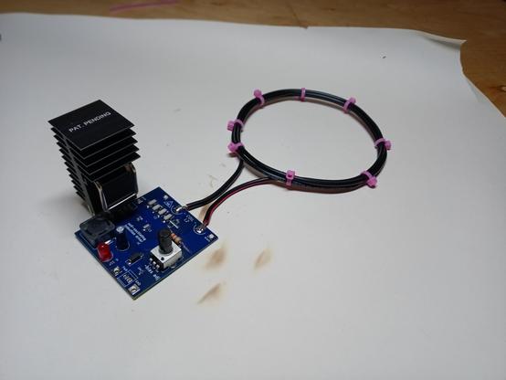
The field-wiggler is operational, at least partially.
Pictured: wirelessly lighting an ampoule of neon.
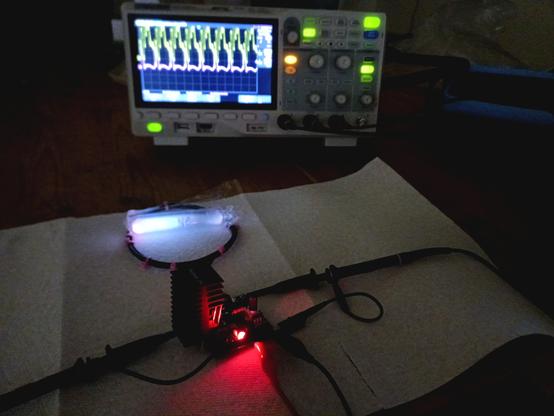
Problems:
- getting some higher frequency noise on the mosfet gate, probably some sort of parasitic resonance. May or may not be significant.
- drive coil gets *really* hot, fast. 18ga wire apparently isn't adequate for this much RF power?
- I've blown up three out of my five mosfets (and that's not an inexpensive component). Worse, I'm not sure exactly *why* they've failed.
I could buy litz wire.
(Thanks @Hearth for offhand mentioning litz wire years ago!)
Ultimately though I do want this to be a PCB coil which should be fine? 1oz copper traces are 35μm thick so standard current-capacity calculator tools should be applicable.
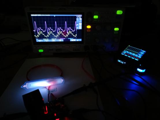
Decided to play with this device a bit more.
Characterized my inductors, made another inductor with only two turns instead of three. I don't have an LCR meter so uhh used the 1kHz calibration output on my scope to ring a little parallel-LC resonator circuit and measured the frequency.
To my great surprise, I also found that the device performs much better at ~12v than the ~20 that other folks have run previously.
Still not sure what exactly is causing the ~100mhz ringing.

update on the ~100mhz ringing:
thought about it some more, and did some more poking at LTspice. While the previously highlighted axial resistor might well be inductive, it's hardly conducting any current. Not nearly enough to produce that kind of oscillation.
My new suspect: the parasitics on the mosfet itself (plus a bit of pcb trace) are acting as resonant LC circuit. Turns out this is totally a known phenomenon if external gate resistance is too low. I had been thinking of my 2Ω2 gate resistor as part of a phase-shift RC circuit (that's how it was presented in previous work I'm referencing), but it also is dampening the parasitic LC resonance.
Here's a video of a lovely gentleman going in-depth on mosfet gate ringing and necessary resistor values

should be able to test this tomorrow.
and I'm... having this feeling like I've rapidly departed from "dabbling at some electronics" and entering territory of "this legitimately qualifies as electrical engineering".
it's a funny feeling.