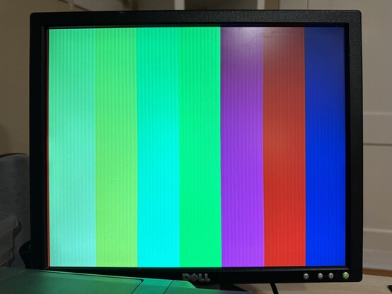
Well, I’ve got colors. Although, not the colors I want. The “white” is very yellow. They are all very dim. And I have these vertical bars appearing as well. Not sure what’s causing that.
Well, I’ve got colors. Although, not the colors I want. The “white” is very yellow. They are all very dim. And I have these vertical bars appearing as well. Not sure what’s causing that.
@tedchoward I think you calculated for 3.3 V drive, but up to what voltage does the Upduino actually drive?
Additionally there's output impedance of the IO pins, which would have to be considered an additional resistor in line. Given that for white, (according to the schematic you posted before) you have 3 pins driving red and green each but only 2 for blue might explain the yellowish white.
@andreasbombe I measured out of the IO lines of the upduino with my multimeter, it was close to 3.3.
What you say about the impedance of the IO likes makes sense, I think. How do I integrate that into my calculations for the resistor values?
Even with only 2 lines, if I get the resistor values correct, I should be able to get a near perfect white. Or am I missing something else?
I appreciate your patience. I’ve been a programmer for 20 years, but electronics is brand new to me.
@tedchoward I'm mostly a programmer myself and am not a really deep electronics expert. I just happened to make a resistor DAC for VGA myself . It's attached with my calculations for an idealized IO pin (3.3 V zero impedance) and and although I haven't really used it yet, the test output looks pretty okay as far as I remember.
I would say your best bet to avoid the color stain is to make the blue channel symmetric with the other ones, i.e. driven by 3 pins, if you can spare another pin.

@andreasbombe Thanks for sharing this!
The reason I’m only using 2-bits for the blue channel is so that I can store a color definition in one byte. Adding the third bit for blue means that I have 9-bits for color definitions which feels like it will be annoying to program for on an 8-bit system.