RC2014
As I mentioned in RC2040 earlier last year I finally got myself a RC2014 – something I had been planning on doing for ages. From the website:
“RC2014 is a simple 8 bit Z80 based modular computer originally built to run Microsoft BASIC. It is inspired by the home built computers of the late 70s and computer revolution of the early 80s. It is not a clone of anything specific, but there are suggestions of the ZX81, UK101, S100, Superboard II and Apple I in here. It nominally has 8K ROM, 32K RAM, runs at 7.3728MHz and communicates over serial at 115,200 baud.”
I’ve had a lot of fun with it over the last 9 months or so, but only a small amount of that has made it to my blog. Mostly because I’ve been catching up with stuff the community has already been doing for some time, so didn’t really feel like I had much that was unique to say.
I’m still not sure I’m at the point where I’m adding to the global knowledge pool of RC2014, even by my “reinventing wheels” standards, but I am at the point where I need to start making some “notes to self” about it, so I thought it was about time to start a proper post on the topic.
RC2014 Classic II
I got myself a RC2014 Classic II figuring that would be a suitable outlay to get started, and it was a good choice for me. Enough going on to get interesting, but not too expensive to start with.
This is made up from the following:
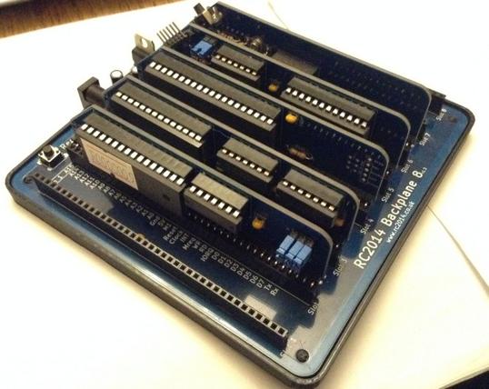
- Backplane 8
- Z80 CPU (a variant of this one) fitted with a Zilog Z84C0010PEG, which can go up to 10MHz.
- Banked ROM – a 64K 27C512 ROM providing 8 ROM banks selectable via jumpers. It comes pre-programmed with ROM R0000009 (details here). The R indicates Microsoft BASIC in bank b000 and the 9 indicates the SC Monitor in bank b111.
- 32K RAM – a single 62256 SRAM chip mapped onto address 0x8000.
- Serial I/O (a variant of this one) – a single serial port, running at 115200 (assuming the standard 7.3728 MHz clock for the system), based on the MC68B50.
- Clock and Reset – the aforementioned 7.3728MHz clock plus a reset switch.
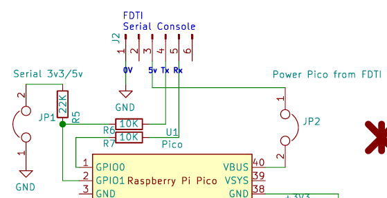
- 5V, USB-C, FTDI module from 8086 (optional). More details here.
The modules provided in the Classic II are not available on their own, as far as I can see, only as part of the Classic II kit.
I’ve made the following small customisations:
- As can perhaps be seen in the photo, I have a simple 3D-printed “buffer” for the PCB to sit in.
- I’ve added the 7805 regulator so it can be powered by 7-12V via the barrel jack instead of the 5V via the FTDI link.
- I went and connected up the additional slots on the backplane, as described in an earlier version of the page for the kit on rc2014.co.uk. But then realised that later versions of the PCB has all slots connected by default. Spencer has since updated the page to say that this is no longer necessary 🙂
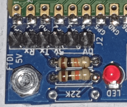
- I’ve put in a higher value resistor as I found the LED very bright! The original specifies 330R. I ended up with 5K.
VGA Terminal
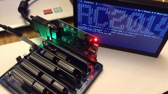
A mentioned in a previous blog post, I spent a bit of time trying out the Raspberry Pi as a serial terminal and managed to get something working quite nicely. But eventually I caved in and picked up the RP2040 VGA terminal. This works really well, but of course the issue is that is requires a VGA monitor.
I found a pretty cheap, small, and neat display that in addition to USB-C power and HDMI input also incorporates a VGA input. Interestingly it also has a composite video input. Mine had a typical key-word heavy title of “7 Inch Portable Display IPS 1024×600 LCD HDMI-compatible VGA AV Input DC Type C Power In for PC Laptop Camera TV Box DVD Screen” on an overseas marketplace and can typically be found for around £30-£35. I found that 7″ is quite a nice size for the RC2014 text.
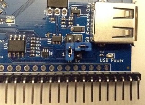
As I’m still using the serial link to my laptop for a keyboard, the UART jumpers on the RP2040 VGA must be set as follows:
- TX: UART 1
- RX: Not connected
Without changing the RX jumper the keypresses over the serial link are not registered. I’m guessing this is because two things are trying to drive the serial I/O bus. I’m not sure if this is an officially supported configuration, I expect it is assumed that a USB keyboard would be used, but it seems to work for me. Shown below.
Audio Boards
I have a few different audio related boards:
- Ed Brindley’s RC2014 YM/AY Sound Card. This allows the addition of an AY-3-8910 or the Yamaha equivalent, programmable sound generator chip to your RC2014. Assuming you can get a chip of course. There are some great notes on this board here and some additional notes on using them with an Arduino here. Note: I have revision 5, not the latest as shown in the repository.
- Why Em-Ulator Sound Module. This is basically the same as the above card, but uses an AVR chip to emulate the AY-3-8910 which completely side-steps the issue of how to get hold of a device. One really neat feature is the addition of a 40-pin DIP socket for purely cosmetic reasons. If you have an old 40-pin DIP chip you can stick it over the emulator circuit and it will look like the real thing!
- SID-Ulator Sound Module. This is an equivalent card for the (in)famous SID chip (Sound Interface Device) as used on the Commodore 64. I never had a C64, but have watched some of the really cool stuff that Shiela Dixon does with the SID, so am looking forward to having a play at some point.
- MG005 Speech Synthesiser. This is a RC2014 board from Mr Gelee’s Tech, for the SP0256A-AL2 speech synthesizer chip (there are some notes here). It is actually quite a lot of fun to play around with.
- MIDI Module, designed for RC2014. This is a MIDI module by Shiela Dixon based on the same 68B50 device used on the standard serial I/O module.
Miscellaneous Other Boards
The RC2014 is definitely one of those systems, for me at least, where it is very tempting to try to get “one of everything”. And following the RC2014 Assembly last year, I’ve a few additional boards stacked up that I’ve been playing around with a bit.
- Digital I/O – This provides 8 LEDs as OUTPUTs and 8 switches as INPUTs, which can be accessed via the IN/OUT instructions to Port 0.
- MG017 I2C Interface – This is another module from Mr Gelee’s Tech that provides a link between the wide range of I2C devices that exist for an Arduino environment and the RC2014. It does that by basically including an Arduino on the board.
- RC2014 Assembly Badge v1.0 – Having visited the RC2014 Assembly last year, I came away with the event badge, which itself is pretty neat too. There is a Hackaday write-up here.
- MG008 ZX Spectrum Peripheral Adaptor – This allows some ZX Spectrum hardware peripherals, that would usually plug into the edge connector of a Spectrum, to possibly be used with an RC2014 system. I would love to get some of my old Spectrum devices recognised, but this will be quite a lot of work to get going. This is on the “bigger” things to-do list.
I also have a 5-way backplane and additional power/reset module from SCC.
Other RC2014 Systems
Not content with the basic Classic II, I also have the following which I keep tinkering with in various combinations.
- RC2014 Micro – This is the main Z80 CPU, ROM, RAM, clock and reset on a single card. But otherwise is essentially the same as the Classic II in functionality. It is particularly pleasing how all the chips are packed onto this single RC2014 module.
- RC2014 Mini II Picasso – I kept looking at these ever since they first came out and resisted. But then one day caved in, and I’m really glad I did. I love this little board. It is a reworking of the RC2014 Mini II, which itself is another version of the Classic II or Micro functionality but in a single module.
Small Computer Central
As well as the original RC2014 there is a whole range of compatible, extended and expanded devices out there that started with the Z80 and RC2014 bus standard. One particular set of extensions is based around standardising extensions to the bus in a way that allows for up to 40 additional signals.
Small Computer Central is the home of the SC Monitor programme that comes with the RC2014 as well as a wide range of computers and modules supporting the various RCxx bus standards: RC2014, 40-pin RCBus, and 80-pin RCBus. The standards are defined here.
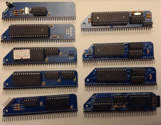
After meeting Stephen at the RC Assembly, and coming away with some of the SCC boards, I’ve been experimenting with some alternatives to my initial Classic II setup. Here is my SCC-board RC2014 equivalent.
On the left, my original RC2014 Classic II modules. On the right, my SCC replacement modules:
- SC149 Z80 Module (RC2014) – has a built-in 7.3728MHz clock source onboard and a Zilog Z84C0008PEG CPU.
- SC150 Paged RAM Module (RC2014) – this is a 128K paged RAM module meant to be paired with the equivalent paged ROM module. The expanded memory compared to the original Classic II should allow it to run CPM.
- SC151 Paged ROM Module (RC2014) – the 128K paged ROM module supporting the paired RAM module. Based on a SST39SF010A 128K Flash ROM.
- SC139 Serial 68B50 Module (RC2014) – a replacement serial I/O module that has the option of its own clock and more address options.
Together, the expanded ROM and RAM should allow the Classic II to run CPM once some additional storage is provided. For me that will be in the shape of:
- SC604 Compact Flash Module – This should allow me to be able to use compact flash as the “disk” for a CPM installation. strictly speaking this is a RCBus module, but it states RC2014 compatibility too. But I’ve not built it yet. Watch this space…
These are all part of the SCC RC2014 compatible range. There are other ranges for RCBus based on the Z80 and Z180 in a range of form factors.
RC2014 Emulation
As well as a range of actual Z80 based computers, as code exists to emulate the Z80 on more modern microcontrollers (usually) there are a number of projects that have popped up with kits that can emulate the RC2014.
I have the following that I’ve been playing with:
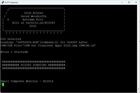
- RC2040 – This is an emulation of a CPM compatible RC2014 system, running on a Raspberry Pi Pico. My notes about getting this up and running can be found here: RC2040.
- Pico RomWBW – A version of the RC2040 geared up to run RomWBW. This is particularly nicely packages, especially if you go for the wooden box.
Software
The basic system comes with Microsoft BASIC and the SC Monitor. Two common aims for these systems are to run RomWBW or CPM (although RomWBW is another monitor that also allows running CPM – so is sort of a superset of the others as I understand things).
Options for running CPM from here:
- Get a Classic II CPM Upgrade kit – this expands the memory and adds CF storage, but reuses many of the parts from the original Classic II.
- Get a Mini II CPM Upgrade kit (and use it with my Picasso) – this is an second board to add to the Mini II with everything that is required.
- Use the SCC RAM/ROM replacements for my Classic II with the CF Storage.
- Use RC2040 or Pico RomWBW.
Emulation would get me going, but I want to get a non-emulated system up and running too. For now that means working on the SCC modules, which to be honest, was essentially why I got them in the first place.
Conclusion
Getting your first RC2014 style kit starts a journey down a bit of a rabbit hole, but it has been a lot of fun so far. The peak was the RC2014 Assembly last year and seeing what so many others are getting up to.
But if you’ve read this far, you’re probably thinking something along the lines of “wait, this is all just building modules – has he actually done anything with them?” And you’d essentially be right. In one way the writing of this blog post is partly to avoid actually getting on with something with the things I’ve now built.
But I do have a few aims of what to explore next, so assuming the agony of choice isn’t too much, leading to another blog post in support of continued procrastination, here are some of the ideas I’ve had kicking around for the past 9 months or so:
- Play with the Pico RomWBW that I got from the Assembly. I’ve built it but not really used it.
- Get the SCC alternative modules up and running and CPM installed on some “real” hardware.
- Have a proper look at the SID-Ulator. I’ve already had a bit of a play with the Why Em-Ulator, but only as a starting point.
- Get MIDI up and running. I’ve had the MIDI board for a while now, but haven’t really done anything with it yet.
- Do some proper music related stuff with the AY-3-18910/Why Em-Ulator.
- And at some point I’d like to build my own module to get a feel for how things like address decoding all work.
So, watch this space. But don’t wait 🙂
Kevin