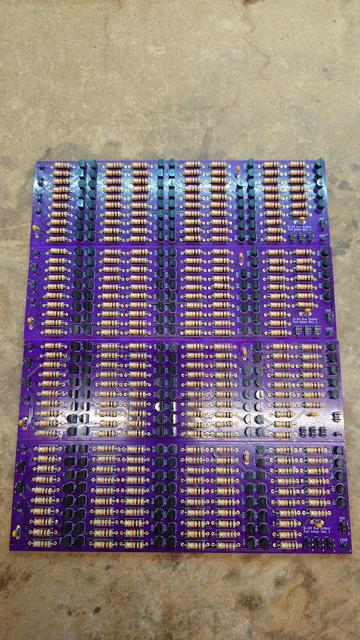
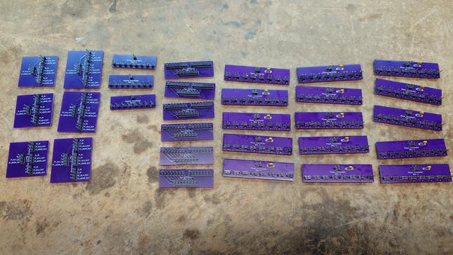
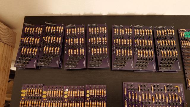
Anyway, I have the designs and parts brought up to make one more acrylic board of the ALU, and after bringing up the other adders I'll be able to make another acrylic board. That leaves just the shifter circuits to be designed, fabricated, brought up and then placed on board number 5 to complete the ALU. When it rains, it pours.

#MiniDragon

Actually got to it and have the first half of the 16-bit adder laid out completely. I still need to dremel a chase on the top for some bus cables before connecting it, but this is the whole thing wired up properly! Tomorrow I'll do the dremeling and then wire it in and then re-test everything with the permanent setup.

#MiniDragon

Procrastinated on actually putting together a MiniDragon acrylic board by updating the layout KiCad file to include the upcoming adder circuit. Neat, the documentation is now more up-to-date than the actual CPU.

https://github.com/dragonMinded/minidragon

#MiniDragon

GitHub - DragonMinded/minidragon: Hardware and software files for the MiniDragon CPU.

Hardware and software files for the MiniDragon CPU. - DragonMinded/minidragon

GitHub

Tonight, instead of doing another bring-up stream, I focused on a tedious but important task on the MiniDragon: identifying and labeling the MSB/LSB on each bus connector. And by that, I mean the most significant bit, and least significant bit. Most of the components are bit-order agnostic. As long as you output the same order you input, they'll work. But, now that everything is piped together, there needs to be an agreed-upon bit order! So, I did that!

I do have some old physical layout documentation that dictated my conventions at the time, and I've verified those are upheld. But, the labels are way easier to read and see.

#MiniDragon

Alright. I excitedly filmed a demonstration of the adder circuit integrated with the ALU and working properly. Please pardon my math mistake partially through where I got super confused about 15+5 coming in at 4. I explain in the video description what's going on there. Please check it out, this is about 5 years of work on and off to get here :3

https://www.youtube.com/watch?v=hHq58udeiqo

#MiniDragon

MiniDragon ALU Adder Circuit Integration

YouTube

dfghdoihgdoifghdifogh the ALU is WORKING.

#MiniDragon

Brought up two more 2-bit adder boards tonight on stream. After testing them individually I tied them to the existing two for shiggles. Behold, a 8.5" by 7" stack of boards that adds two 8 bit numbers with carry in and carry out. I got 4 more to bring up at some other point to have a functioning 16 bit adder, which I need in order to do indirect addressing and manipulate the instruction pointer and stack pointers (relative jumps, moving the stack pointer forward or reverse by an immediate or the A register, etc) and have arbitrary access to all 64K of memory.

#MiniDragon

tonight's meditative assembly was a bunch of distributor boards that i need for future panel layouts. the only components on any of these that aren't just pin headers are a bunch of capacitors on the power distributor boards. still, they make wiring boards to each other much easier and give things a bit of polish.

#MiniDragon

I recently made a tiny collection of dragons - so i'm trying out doing a print of them collected together. #dragons #dragonart #minidragon #watercolour #painting #prints get yours here: buff.ly/rUmKeem
Bluesky

Bluesky Social

And then there were 14!

#MiniDragon

×

Tonight, instead of doing another bring-up stream, I focused on a tedious but important task on the MiniDragon: identifying and labeling the MSB/LSB on each bus connector. And by that, I mean the most significant bit, and least significant bit. Most of the components are bit-order agnostic. As long as you output the same order you input, they'll work. But, now that everything is piped together, there needs to be an agreed-upon bit order! So, I did that!

I do have some old physical layout documentation that dictated my conventions at the time, and I've verified those are upheld. But, the labels are way easier to read and see.

#MiniDragon

@dragonminded where/how do you get your plexiglass / acrylic mount plates?
@violator years ago (about 5 at this point) when i was still buying from amazon i bought them from a seller who had a bunch of precut 12"x12" acrylic plates. i drill the corners with a template. i have a fair amount left but after that i'll have to find another source since i don't give bezos my money anymore.
@dragonminded i've sourced it frequently from mcmaster, but never for personal use due to cost
@violator oh hmmm mcmaster~ let me look at what they charge. i know tap plastics will sell you cut acrylic sheets as well but i don't think i'm close to one anymore. i'm also betting you there's ebay sellers selling the equivalent of pre-cut, and probably somebody or two on etsy as well.
@dragonminded yeah. I might also be a bit on the cheap/lazy side. I know there are some local shops as well, but that involve a whole ~thing~ and interacting with people. protolabs solves that at a cost though
@violator looking, mcmaster wants $11.44 per 12x12x1/8" acrylic sheet which feels a bit steep, compared to normal mcmaster prices. i don't remember what i got this 12x12x1/8" stock for but given it's made in china and comes from amazon it was probably about $10 per pair of sheets.
@dragonminded they have a bunch of acrylic options, i think the cheapest I see is on this page at $7.33, but I don't know if that's equivalent to what you've gotten in the past / adequate: https://www.mcmaster.com/products/plastics/plastic-1~/clear-high-strength-scratch-and-uv-resistant-acrylic/
@violator ah yeah you found the same one i did, lmao.
@dragonminded they have coloured acrylic too. think you'd colour-code your computer?
@violator honestly i didn't think about that but that sounds fun honestly. registers one color, alu boards another, instruction decoder boards another. miscellaneous logic another. would be fun.
@violator i'm already color-coding individual circuits based on the LED color. red = registers, memory and D/T flip flops. basically anything with state. also for basic logic components such as and/or/not/xor/equality/etc. yellow = encoder/decoders such as 1-to-2 and 2-to-4. green for bus circuits. blue for instruction decoder signals.
@dragonminded the big blink. i've probably asked this before, apologies if repeating, but did you establish this in an hdl before starting the hardware effort?

@violator nope~

i have a software simulator for the whole thing, and i've been bringing up boards bit by bit (sometimes literally) to fill in the needed hardware components.

@violator honestly given this is RTL (TTL-compatible) and with a limited BOM I feel like trying to design it in a HDL first would probably be a mistake, because I'd have to modify that design for the physical manufacture.

For instance, I don't have any tri-state logic. I use pull-down busses instead. I wouldn't have designed it that way in HDL. I would have assumed normal tri-state.

@dragonminded fair, that said my intuition would have me thinkin it'd be easier to model the timing with an hdl+sim than implement it in a software sim, but i've always been a poor implementer of software

@violator i wasn't worried about timing so much as general feasibility. and for that, the simulator was key, because it let me validate assumptions with the microcode as well as optimize the stdlib and test instructions. it also means that i can just generate the microcode "programming" instructions for a given instruction right out of the simulator.

timing is so much looser on this thing. it's gonna run at like 10-20khz. the biggest timing worry was around edge detection which is accomplished using an RC circuit on all the latched components, and that's entirely in the analog domain. i guess propagation delay comes into play, but given the slow clock speed it's mostly meh. i think with the propagation delay of most of my circuits being so high (individual BJT transistors and 1/2W resistors do not change "state" quickly) it could only theoretically run at around 100khz anyway? the speeds you can get in a more modern setup are all due to miniaturization.

@dragonminded makes sense
@violator i ran some experiments seeing if i couldn't get the circuits "faster" through various means. i could have also experimented with DTL instead of RTL and gotten it closer to standard TTL design. i could have dropped some of the resistances to up the current and make some stuff faster to transition. i played with "speed-up capacitors" based on internet research, and they did nothing. i played with different resistor values and it made minimal impact. most of my circuits are in the 2-5uS propagation delay range, which would mean maximum clock of 200Khz assuming the worst signal path was only one board deep. it's not, though, and many signal paths go through several boards, so divide that maximum click rate by 5ish. i don't want to mess with variable clock timing, and it's already microcoded meaning different instructions take different number of clock cycles, so a lot of speedup occurs by minimizing the required number of microcodes for a given instruction.

@violator basically, if i wanted to bump the clock on this i would have to take some safety paths out of some of the designs and combine physically separate boards into combined boards, since a lot of the delay comes from current-limited inputs and buffered/amplified outputs to make sure board have high fanout and don't load the output of the previous stage unnecessarily.

ultimately the compromise was to make this physically manufacturable and debuggable over the fastest design possible. the more complicated the circuit, the more times you gotta send it to fab and rework it based on bring-up flaw finding. hence why i dropped from a 4-bit to a 2-bit adder. i was getting the 4-bit one working, but slowly, and with $100+ runs each time it was just eh. so i dropped to a 2-bit. that means more propagation delay for the carry to ripple, but crucially it also means i can actually complete it.

@dragonminded yeah, the course to miniaturization comes with complexity. as a tangent, i've been keeping the two definitions of RTL and my understanding of them nice and cleanly separate in my head for all these years now, but i can't recall a single time where I didn't mix them up when someone asked
@violator for the purpose of minidragon, you can just assume TTL, because the voltages are compatible. the actual implementation is RTL, but i'm planing on interfacing with TTL-compatible CMOS circuits for all the external stuff.
@violator best i could get on mcmaster with more generous filters is https://www.mcmaster.com/4615T93/ which is not bad per panel ($7.33 per). let's see if tap plastics can beat that.
@violator yep. tap plastics can get me the exact same 12"x12"x1/8" panels for $4.94 each. they also have physical stores you can go into if you're in a bunch of metro areas in the usa. https://www.canalplastic.com/products/clear-colorless-acrylic-sheet?variant=32920770318
Clear Colorless Acrylic Sheet

@violator ebay can't even begin to compete. i gotta randomly click through sellers and for 1/8" thick sheets a 12x12 starts at around $15 each from the sellers i'm looking at.
@dragonminded acrylic: sourced. no stores in this desert though, such is desert life
@violator i figured tap would come through. i've used them for a variety of custom cut plastics for cabinet restorations before and they've been reasonable. i used to have one a block from my house in the bay, now i have to use them online. but, $5 a sheet is hard to beat.
@violator oh hmmm lmao i got canal and tap mixed up in my urls. let me see what tap does.
@violator okay tap can't match that at all, they start at $15 a panel. if i order 8 it goes down to about $9 a panel which is on par with mcmaster. so canal plastics above seems like the best bet. i think they keep their prices down by having 12x12 be one of the pre-cut options.