Guide to the TD4 4-bit DIY CPU
https://www.philipzucker.com/td4-4bit-cpu/
#HackerNews #DIYCPU #TD4 #4bit #Technology #Hardware #HackerNews
Guide to the TD4 4-bit DIY CPU
https://www.philipzucker.com/td4-4bit-cpu/
#HackerNews #DIYCPU #TD4 #4bit #Technology #Hardware #HackerNews

RT @Maor_Elkarat: Hör auf, mehr VRAM zu kaufen.
mehr auf Arint.info
<p>RT @Maor_Elkarat: Hör auf, mehr VRAM zu kaufen.</p> <p><a href="https://arint.info/@Arint/116527049491718972">mehr</a> auf <a href="https://arint.info/">Arint.info</a></p> <p>#4Bit #AI #Grok #KVCache #Qwen36 #VRAM #arint_info</p> <p><a href="https://x.com/Maor_Elkarat/status/2050866949643477241#m">https://x.com/Maor_Elkarat/status/2050866949643477241#m</a></p>
TD4 4-bit Sound
Over on my other blog, I spentt a fair bit of time looking at the TD4 4-bit CPU. One of the things I wanted to do with my NAND Oscillators and Logic Sequencer PCB was hook up the address/select pins to something else. And with three select pins, allowing the choice between 8 notes, what better to connect it to, than a 4-bit CPU?
https://makertube.net/w/aroDZYM2BHYpoB9QLJvHnk
Warning! I strongly recommend using old or second hand equipment for your experiments. I am not responsible for any damage to expensive instruments!
If you are new to microcontrollers, see the Getting Started pages.
Parts list
The Setup
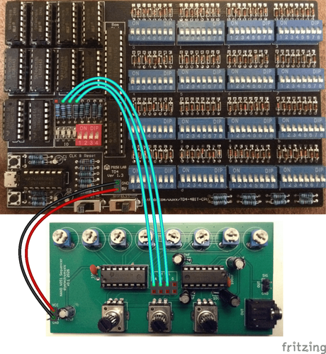
The most obvious thing in my mind, is to hook up three of the four outputs to the three selection pins of the NAND sequencer, so that is what this post explores.
The NAND PCB needs the jumpers removing, which disconnects the pot-driven oscillators. Then the three select/address lines can be connected to three of the four resistors supporting the OUTPUT LEDs of the TD4, as shown above.
It is also possible to use the POWER header pins to power the NAND PCB too.
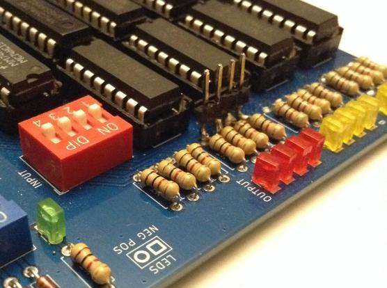
Any of the variants of TD4 I’ve built could be used, but I’ve shown above where they would need to be connected on the original. In the end I actually soldered four header pins to the appropriate side of the resistors on my own PCB version of the TD4 as shown below. A bit crude, but it does the job.
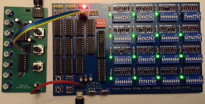
Connecting these over to the NAND sequencer and hooking up power gives me the following.
The Code
The simplest way to create a sequence is a set of OUT xx instructions where the least significant 3 bits (so values 0 to 7) map onto the three possible notes played by the NAND sequencer.
This is the simple LED OUTPUT code from Part 3 of my series, but this continually toggles between the lowest and highest notes.
0000 OUT 0001 # 1000 1101A counter can be used to play all 8 notes. Note that in this code B will go from 0 to 15 (b0000 to b1111) but only the last three bits select notes. This means that the sequence will count from b000 to b111 twice for each pass through this loop with the top bit being ignored.
0000 ADD B,0001 # 1000 1010There are only two speeds though, 1Hz and 10Hz so the above, which has three instructions, has a tempo of 20 bpm (1 note every 3 seconds) or 200 bpm (approx 3 notes every second). The tempo can be slowed down in steps of 1 second or 1/10 second by moving the JMP an instruction further down and back-filling with other instructions (ADD A,0 or b00000000 is a good one, and is essentially equivalent to a NOP).
The following code uses the INPUT as a counter in a loop to provide a partly configurable tempo.
0000 IN A # 0000 0100 A = INPUTThis is still only cycling through each note individually though, but that is kind of what an 8-step sequencer would do.
To get more creative with the programmability of the sequencer requires a series of OUT instructions and NOPs between them, for example:
0000 OUT 0000 # 0000 1101 OUTPUT = 0000 # Play note 000This last programme is the one running in the video at the start of this post.
Closing Thoughts
I appear to have made a sound card for a 4-bit CPU 🙂
One thing I am quite keen to do is connect up the sequencer’s select pins to the TD4’s address lines, as I’d like to be able to have some incidental (accidental?) music that appears as a result of the CPU just running any other normal programme.
To do this I’d need to either hook into the output of the PC register or the input to the HC154 ROM decoder.
In fact, it would be really interesting to be able to hook up any sets of four signals – so the INPUT selector, or even the control decoding logic – just to see what it sounds like as the CPU is running normal code. That might require a special build of the CPU though.
I also have an address line spare of course, so it would also be interesting to use that to select between two NAND sequencers to give me a 16 step sequence.
Kevin
TD4 Sequencer and NAND Oscillators

NVIDIA công bố đột phá nén mô hình từ 16-bit xuống 4-bit với độ chính xác giữ nguyên tới 99.4% – gần như không mất dữ liệu. Công nghệ này hứa hẹn thu nhỏ kích thước AI, tăng tốc độ xử lý và tiết kiệm năng lượng, mở đường cho AI nhỏ gọn, hiệu suất cao trên thiết bị di động và biên. #NVIDIA #AI #MachineLearning #AICompression #4bit #AIHiệuSuấtCao #TríTuệNhânTạo #NénMôHình
RE: https://mastodon.online/@fortifieduniverse/115747090594432106
I use all of their products almost constantly when I’m in the box, so super excited to check this out a bit later today. #fors #softsynths #wavetable #4bit
The PCBs work! Here it is in action. Now with extra bling! :)

TD4 4-bit DIY CPU with Arduino Nano ROM
And here is the accompanying blog post describing the theory and design.
https://emalliab.wordpress.com/2025/11/26/td4-4-bit-diy-cpu-part-8/
