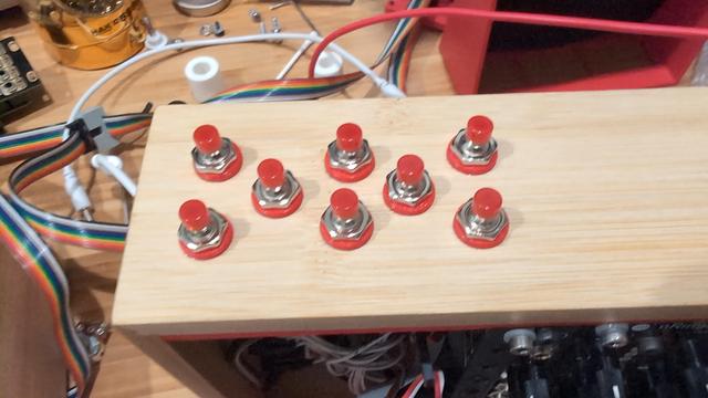
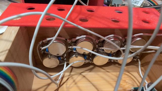
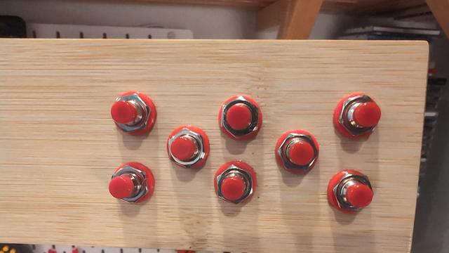
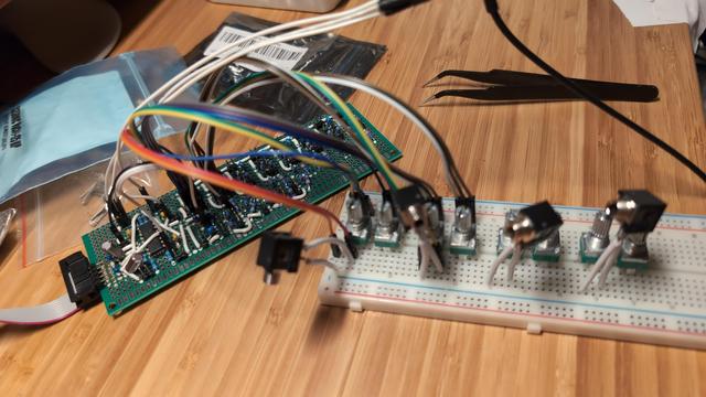
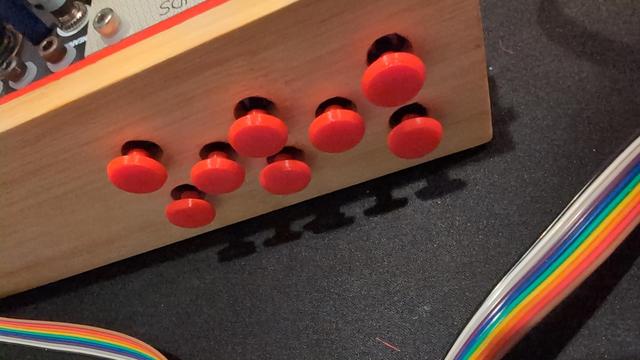
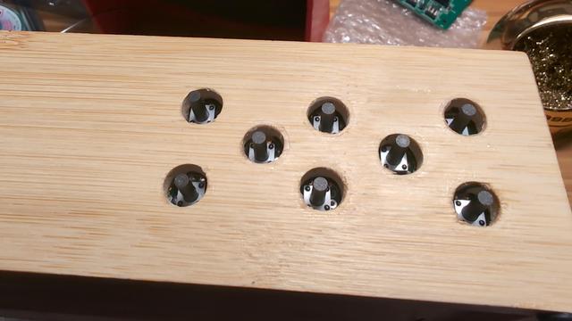
288 Followers
353 Following
6.8K Posts

They/them online pseudonym. Anti-capitalist, anti-religious, anti-spiritual, anti-AI, anti-fascist. I was apparently raised in one of the more relaxed branches of a cult.

I don't have a fleshed-out political theory yet. I'm not sure I can attain to one, but I belong somewhere among the anarchists and socialists.

I make music, pottery, food, repairs, software, and hardware. I boost much more than I post, but I don't boost images without alt-text.

Fascists fuck off.

#nobridge #nobot

Digital Gardenhttp://lyk.so
Bandcamphttps://mumbleandsigh.bandcamp.com
Mirlohttps://mirlo.space/mumbleandsigh
Codeberghttps://codeberg.org/lykso
Seen about town.
Made this badge for my MIDI mixer firmware repository. You're welcome to use it too, if you like.

Been working on this long enough and have made enough progress that I reckon it's about time I share something.

This began as a MIDI mixer project and has grown into a still-being-defined sequencer/synthesizer project. I still need to make and route cables, write firmware, and get the power supply and MCU board installed before it can start working as a MIDI mixer, but it's just about there. Next steps involve learning how to work with capacitive touch sensing.

#diy #modularsynth

Managed to work out alternative jumper positions allowing for basic functionality. Here's a clip of the module I designed turning LFOs from a Just Friends into a sequence of gates and sending them out to another Just Friends, a BitBox, an nRings, and a Manis Iteritas Alia, with a little extra modulation on the nRings from an ochd.

Recorded on my phone with a cheap USB-C microphone adapter and heavily compressed to save space on the server, so apologies for the quality! 7.65MB, 45 seconds, 480p.

Alright, proceeded to PCB and assembly with an "omnijack" footprint that should be able to take my own jack design as well as an off-,the-shelf jack (as I used in this video). I seem to have misunderstood a datasheet somewhere along the way, so my "expansion header" and accompanying silkscreened guide are wrong. But breaking out so many things on the header has meant I can at least get a functioning module by replacing a jumper with a Dupont wire. Very relieved for that!

Latest print has a reliable sleeve switch but the tip switch doesn't work. Also very fiddly and annoying to get the copper routed. Printing a version which will hopefully alleviate these issues a bit.

Unsure whether to continue this development or just buy my jacks like a normal person. I've dropped my need for transparent plastic and have found an alternative that meets my size requirements, so what am I even doing this for now?

This design will require bigger through-holes than I'd wanted. Little room for bosses here. But the tip insertion sensing is working reliably so far, at least with this one prototype. The sleeve insertion sensing pin seems to be getting pushed too far up to return to the right position, so I'll have to try adjusting that.

Uses two paperclips per jack.

Looks like y'all are somewhat interested in what I'm doing here, so here's a photo of some of my attempts.

The two big rows in front were my first, as I plan on making this an LED and jack assembly and foolishly though this would be simple. The one on the perfboard had severe pin mobility problems and was not very forgiving of imprecise wire work. It did at least allow me to confirm my ability to solder a pin connected to PLA without melting it, though.

More details in the alt text.

Nothing caught on fire or blew up, but the module also isn't working. Debugging will have to wait until tomorrow, I guess.

No epoxy yet because I don't have proper PPE for that shit at the moment, and won't until December 3rd at the earliest. Still gonna wire it all up and test it out a bit. Here's a progress photo.

Hope I don't fry anything!