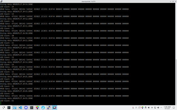
Trying to send string data over an ARGB controller output to set the sizes of the splitter channels. I'm trying to send a string in the format "ARGBSPLIT,0=xx,DONE" where xx is the number of LEDs on splitter channel 0 (eventually to add more LED channels to the string). I've gone through with an ASCII table and manually encoded all the characters into LED color values in OpenRGB and can parse the LED count on the RP2040 side!
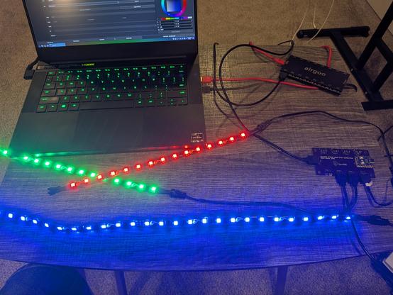
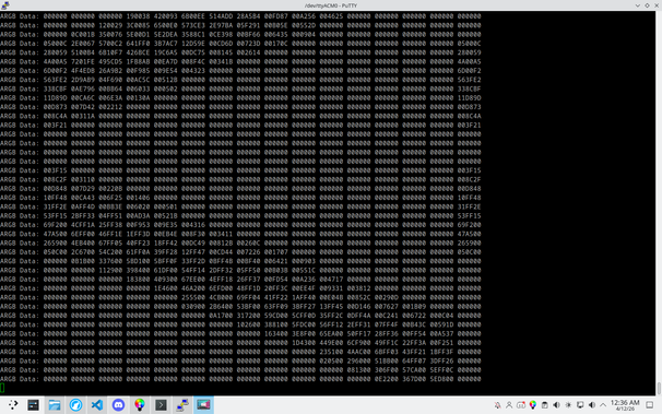
Got it to parse more than 4 channels by using DMA. I set up two 1024 LED buffers and flip/flop between them every time a complete ARGB signal is received (detected by a 50us timeout as defined in the WS2812 protocol). The completed buffer is available for parsing while DMA starts filling the other one. In this screenshot I was printing out the first 16 LEDs while running the Visor effect in OpenRGB (the 16th LED is the first LED on the second strip so it's not part of the same pattern).
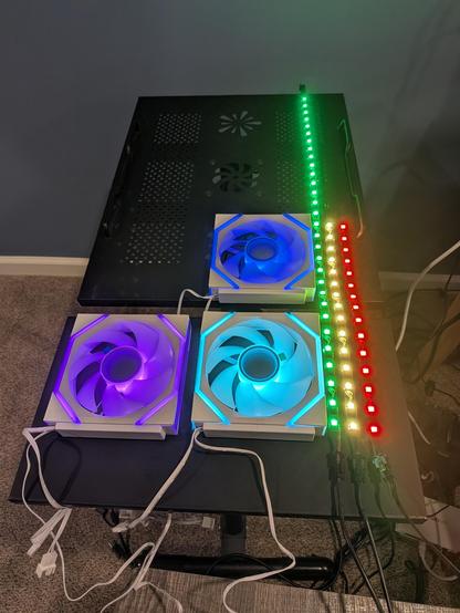
Hooked up some fans. Each fan has 26 LEDs, and the three strips are 15, 15, and 30 LEDs each. The input signal is set to 138 LEDs.
My
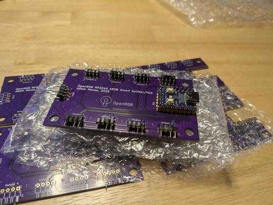
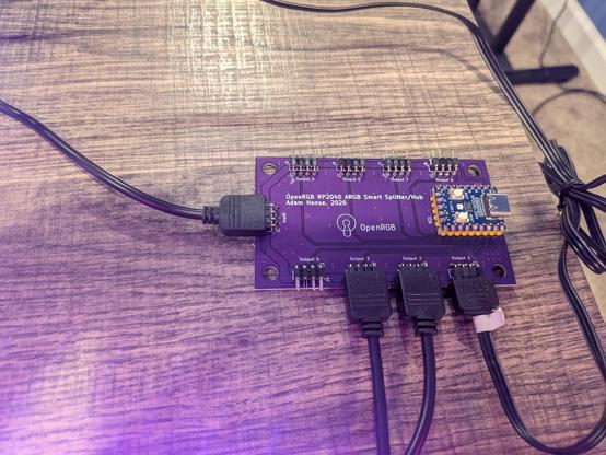
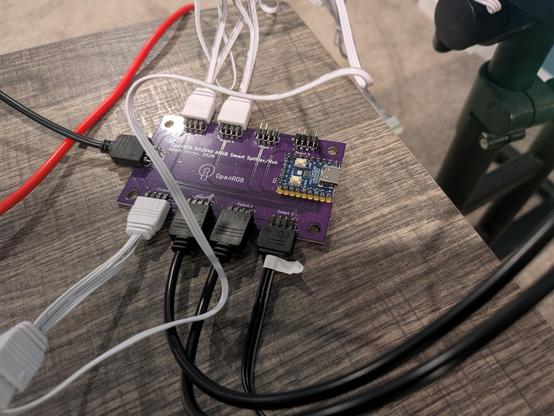
#RP2040 #OpenRGB Smart ARGB Splitter PCBs came!
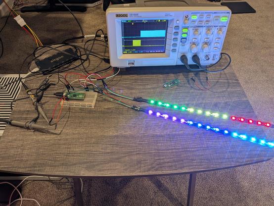
#OSHPark did a great job on them and they work as expected. Splitting one ARGB/WS2812 signal into up to 8 output channels.
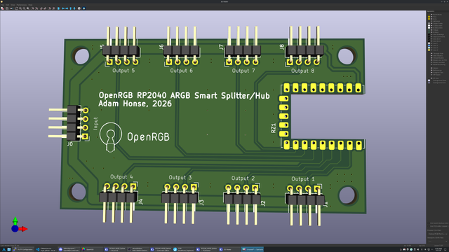
I designed a PCB! I ordered some
#RP2040 Zero (Waveshare clones) because I didn't feel like soldering a bunch of tiny SMD components when a tiny module with them already soldered could be had for under $3. Just needed to route everything out to connectors to make a functional ARGB hub, which could also act as an ARGB controller from the RP2040-Zero's USB port (though it is meant to be powered from the incoming ARGB connector).
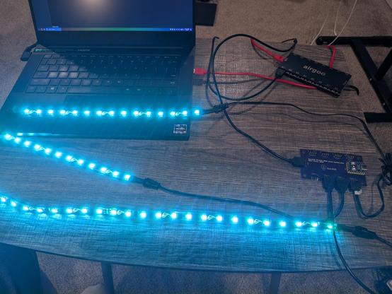
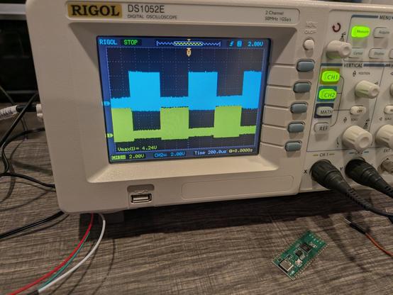
Yesssss! All it needed was the idle reset and to fix an off by one error on the bit counter! Successfully splitting a 30 LED WS2812 stream into two 15 LED streams (actually the controller is sending 255 LEDs but
#OpenRGB is only driving 30). Now to rig up a third output to make sure subsequent switches still work.
Made some more progress for the night. I split the output muxing and clock counting into two separate state machines so they can use their X and Y regs as current and next value, meaning when the PIO interrupts the CPU it doesn't need to respond instantaneously. I got it to where it's switching channels back and forth, and I could feed in different clock counts for each segment in the ISR. Next step is to detect idle time and reset state machines.
ARGB splitters suck. They just duplicate the same signal to all outputs and ruin the addressable in ARGB. I'm attempting to use the
#RP2040 PIO to create a smart ARGB splitter by counting the bits and outputting the signal to multiple pins. I attempted this years ago on an ATTiny, but it was too slow. PIO is fast enough to pass through the WS2812 signal unharmed as well as able to count the bits to know when to switch outputs.?
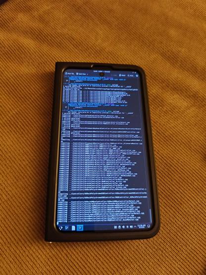
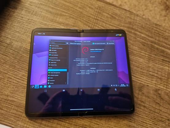
@GrapheneOS After a lot of trial and error, I'm now on track to get a successful OpenRGB compile directly on Termux. Had to set some env vars for pkg-config to work. The Linux VM is still a bit too rough around the edges to do serious work in (limited RAM, missing keycodes, fixed resolution, no VPN) but Termux runs Plasma well, though in X11 and system paths are a mess due to being in the Android environment not a dedicated chroot or VM.
@GrapheneOS This is with the Android 16 Linux VM terminal, the nice part is that it seems to be able to boot a full isolated system with full permissions intact (as it is a separate system running in a VM) as well as run native sessions (installed kde-full and started sddm, logged in). Unfortunately, the GUI is limited to this awful fixed size window with a ton of wasted space and non-native scaling. It is Wayland with proper touch input though which is excellent.