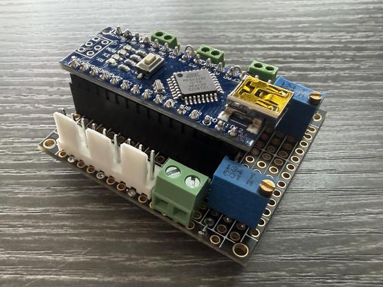
Today’s lunchtime project: nearly completed a prototype of an Arduino Nano based semaphore signal controller. The inputs (green terminals on the far side) are compatible with SigNaTrak’s SIGM20, so you just wire up red (or green) of a two aspect signal. The outputs are straight servo connections. The board requires 5V to work.

The Arduino reads a digital input and uses the value to decide if the associated servo output should be in one of two positions. Those positions are set by the adjustable potentiometers. If the servo isn’t in the right position, it moves to that position, but slowly.

This allows you to connect a small servo to a semaphore signal and drive it from the SIGM20 as if it were a two aspect red/green signal. The board actually supports three servos in total.

I’ll need two such boards to support all the semaphore signals I’m planning to install, they’ll cost me maybe £15 each in this prototype form.

#ModelRailway #arduino #prototype #signalling

If I were to produce PCBs/kits/pre-assembled units they’d be 12V powered (the de facto standard for model railways), they’d have a few more features, support two servos per board, and there would be two variants. The SIGM20 compatible version (which requires a transistor amplifier on each input to boost the 2.8V from the SIGM20 to 5V) and a 12V version (which would use a resistor ladder to drop the 12V input down to 5V for the Arduino. The 12V version would lend itself well to simpler layouts that used switches on a control panel or micro switches incorporated into point motors and the like. No firm plans but I could be persuaded if there is interest!

Next post will feature a video of the assembled unit controlling three separate servos…

Fingers hiding the PCB until the end but here’s a quick demo… using a resistor to +5V to simulate the input to a servo.
@gulfie that’s a heck of a productive lunch!