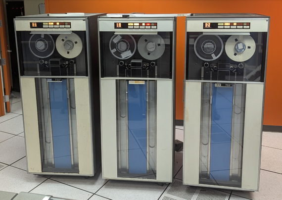
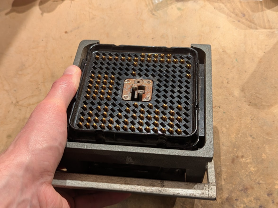
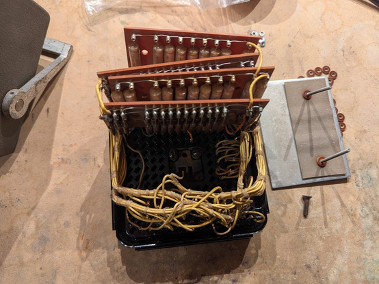
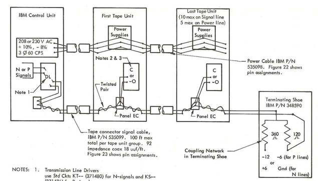
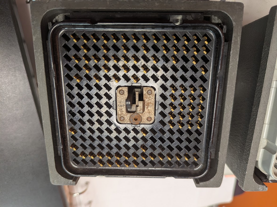
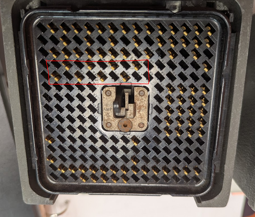
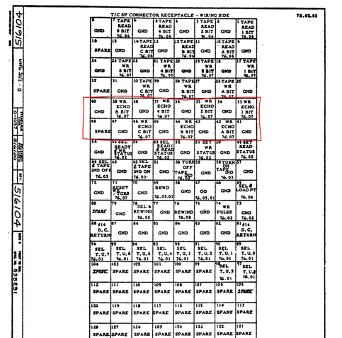
i've been tinkering with IBM tape unit terminators. the 729 tape units were daisy-chained and connected to a computer (such as the IBM 1401) but the end of the line needed this special terminator. it's a giant waffle connector, same as used by the cables.
(oh yeah, the picture of the tape units is somewhat special because we recently fixed all three of the 729 tape units on one of the Computer History Museum's two 1401 computers!)
inside a terminator is an array of resistors that are designed to connect a signal line (data or control) to a termination voltage with an impedance that matches the characteristic impedance of the coax that carries the signal. there are also 5uF capacitors that couple some of the coax shield lines to ground.
the official pinout looks like this. the upper section carries control and status lines. the right section has the tape unit select lines which assert when the computer wants to talk to a particular tape unit (matching the glowing number on the front panel). the left section has the read data bus, and the bottom section has the write data bus.
only signals that originate FROM the computer (and go out to all the tape unit) need the terminating network, which is just a 360 ohm and 120 ohm resistor (equivalent to 90 ohms, the coax impedance). signals from the tape units go into the computer and are terminated there.
this means that the terminator skips certain pins, notably the read bus--see that there are no pins on the left section--and the status signals (tape unit->computer) on the top section.
now what's weird is that the terminator has some EXTRA MYSTERY PINS that are not listed in any of the IBM 729 documentation. see the red box in this image.
ok, one IBM document shows the pins, but in a weird way. the schematics have the pins shown as blank boxes, but in the "tape signal terminator" section, they are listed as type Z pins (response line decoupling.)
the pin list doesn't have those pins either, but it DOES document some "spare pins" -- they are shown as *extra data bits*. the 729 is a 7-track machine, so you have data bits 1, 2, 4, 8, A, B, and C. but this chart has additional bits X and Y!
a clue in the earlier IBM 727 manual! there are pins listed as "echo bits" which are sent back to the computer from the tape unit when it is recording data being written. i think the 729 doesn't include those bits because it uses the read bus to echo the write bits. but for whatever the reason, the shield pin connections were left in place.
yeah looks like the 727 has a dual-purpose single read/write head. the 729 has two sets of heads, one for read, one for write. the 727 needs the echo bus because the read bus doesn't work during a write operation.
my current theory is that the echo bus was included in the IBM 729 Model I because it could be used with older computers that were designed for use with the 727, and expected the echo bus to be there.