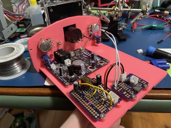
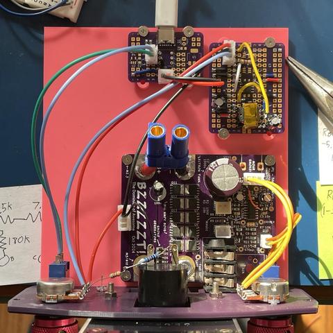
This mess is a LM3748-based SEPIC converter. The idea is this will be the power supply for the pulse welder. All it needs to do is charge up the caps, so it doesn’t need to be particularly beefy or, y’know, good.

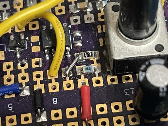
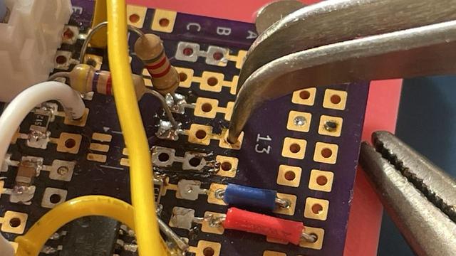
I had it working, blew up the MOSFET, and dropped in (I think) a 2N7002 (which is of course a bad choice). It didn’t work after that, I got frustrated, went to bed, and forgot about it.

Today I came back to it. I pulled up the datasheet, checked all the connections, and everything looked fine until I got to this bit on the FA/SD pin. I thought, “Huh. That’s weird. That’s hooked up to VCC. It’ll never run like that!”

Then I remember this little bit in the datasheet about the FA/SD pin. Apparently I had designed this so that you have to short the middle of those two resistors to ground before it will even turn on. I’m the problem. 😆

With a jumper in place, it runs fine. (Well, not fine, it runs like crap. But it runs.)

Oh wonderful. It makes terrible noises. 😆

There’s two neat things about the SEPIC topology. First, it’s a buck-boost converter. As you can see in the video, it’s outputting between about 3 and 14V from a 5V input.

Second interesting bit is that capacitor in the middle electrically isolates the input and output as well as limiting the amount of current that can pass through it on each cycle. So when this sees what is effectively a short at the empty capacitor bank, it won’t overload the components by trying to shunt all available current to the output.

They suffer from poor efficiency, being effectively a two-stage design. But it’s a good fit for this particular task.

The image is taken from the Wikipedia article: https://en.wikipedia.org/wiki/Single-ended_primary-inductor_converter

I have engaged my brain on this design, and come up with this. The front panel is directly attached to a tray that holds all the boards. This whole unit slides into the case (which does not yet exist in meatspace), so all of the wiring can be done *before* it’s assembled (except for the connection to the capacitor bank sitting on top, which might be a bit tricky).

Now that these two bits are assembled, I can see some problems with the front panel. The 1/4” jack for the foot switch is slightly off, and somehow the slot where the probes come through is too low. But otherwise I think this will work.

Making good progress on the wiring. Not my best work, but it’ll do.

Tested it for the first time and it wasn’t regulating properly. Turns out it works better when you complete the circuit. 😅

The revised front panel is now dark purple. Yes, I could make this in normal colors, but why would I?

Hope your Friday night is as fun as mine. Been dreading rewiring the capacitor bank. It’s not hard, It’s just a lot of heat into thick copper, so pretty much every bit of it is a burn hazard.

Only one last bit left, putting some flexible wires and the EC5 connector on it. And I think I will leave that for tomorrow.

Man, I hate EC5 connectors. You have to more or less melt the housing to press in the contacts from the cable side. And they don’t press in flush with the housing, they’re recessed by a couple mm. There’s probably a proper tool for this, but I’m more or less using a heat gun and needle nose pliers.
Well it’s not pretty, but it’ll work. I assume some kind of crimp connector would have been more appropriate here. Not a lot of room to work with, though. Just gotta do a few LEDs and this will be ready for testing.
CHARGING…
@bytex64 can you add the sound effect of a big contactor closing with a CHONK and then an ascending whine as it charges?
@dtl Haha. If I put in a self-oscillating boost circuit, it probably would whine just like a camera flash. And believe me, the SNAP as it vaporizes metal has plenty of impact. :)