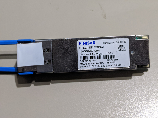
One of my nice friends at Hurricane Electric gave me a dead 100G-LR4 optic to tear apart for your entertainment, so for the sake of your entertainment, lets dig into it! 🧵
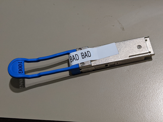
First comes off the ejection bail. I guess we're committed now since that was rather destructive.
Two tiny screws get us into the case. The grey putty stuff is thermal gap filler, which couples each part that puts off heat to the case for cooling.
Think of it like thermal paste, but it's designed to be thick and span a gap instead of just be a thin film.


Lifting the electrical assembly out of the other half of the metal case, we can start pointing out the major points of interest.
TOSA/ROSA - transmit/ receive optical sub assemblies are where the laser magic happen.
The retimers help 4x25G get to the switch via the QSFP connector


And that microcontroller that runs the whole show is... a Cortex M3! An STM32F103C6 with 32kB of flash, 10kB of SRAM, and can run at up to 72MHz.
Meaning that this optic has more compute power than many early home computers.
You'll note that the ST microcontroller is silver, as are a few other ICs on this optic. This is actually a cost saving measure called "flip chip" packaging, where they don't waste the expense of the black plastic packaging and solder the silicon die straight down onto the board like it was a QFN. Absolutely wild.


While it's fun to think about malware on the ARM core in these, the data path is WAY faster than the Cortex M3 can handle. It's entirely an out-of-band manager of the electronics with no idea of what is going on in the Ethernet link itself.
That being said, some newer optics really DO have interactions in the data path. The most notable is the speed-changing optics which allow modern Ethernet switches (which only support 10G/25G/50G on their front panel ports) to still link up with a 1G Ethernet peer. The optic does the 10:1 speed change and implements clause 37 autoneg entirely inside the optic.
Granted, the firmware on optics actually *IS* field writable. I've coordinated with an optics vendor in the past to help a customer apply a firmware patch to 10,000 optics installed in Arista switches in the field by issuing the right magic sequence of write commands over the I2C bus from EOS.

Remember how I said the rest of the parts were mostly voltage regulation?
Voltage regulators usually need some kind of inductance... so just saying... prime cute coil of wire opportunity.


The keen eye will also notice that some of the Dremel debris from me cutting open the TOSA is... stuck to this cube and fuzzy... like it's magnetic...
And it it. That is a tiny magnet in the middle of the optical path, but why?
Physics talk. Remember that the transmitters here are lasers, which mean that the four lasers on the right are each their own resonant cavity, which leaks a fraction of the light to be useful. But if there was some kind of partial reflection out in the fiber somewhere, this could cause problems and destabilize these lasers, so we would like some way to let light OUT of the TOSA without letting any reflected light back into the lasers to cause problems, so we make an optical one-way valve...
MORE PHYSICS TALK: Light is a perpendicular E-M field, so if you used a vertical polarizer, and then passed the light through a magnetic field to rotate the polarization 45 degrees to line up with a //// diagonal polarizing filter on the other side of the magnet...
Think about the reverse path. //// polarizing filter, 45 degree rotation, horizontal light hitting a vertical polarizing filtering. BLOCKED.

Putting the TOSA under my microscope, we can start to see some more of the finer details.
This is rotated from the last photos.
I'm not convinced whether the two missing lenses in the middle broke off before I got it, broke off while I was hacking my way into the package, or were just never there. A mystery for the ages.
