theory and simulation ❌
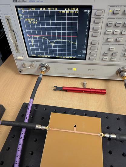
keep cutting down the trace stub until it's roughly on frequency ✅
keep cutting down the trace stub until it's roughly on frequency ✅
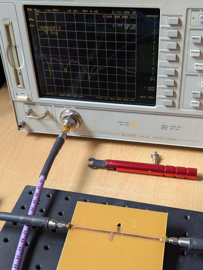
continuing with the copper tape shenanigans, I drilled through the board and shorted the end of that stub to have it notch out ~10 GHz instead. It came out a bit low, so I had to shorten it a couple of times. I guess the copper going through to the back of the board effectively adds some length to the stub.
Then I added another stub to notch 5 GHz again.
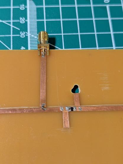
Now for the actual reason for these stubs: I'm trying to make a subharmonic mixer to play around in the 10 GHz amateur radio band.
I cut a gap between the stubs and added a pair of anti-parallel diodes. The stubs should notch out feed-through of the 10 GHz RF and 5 GHz LO.
Then added a third port for the IF output, just through an inductor as a basic low-pass for now.
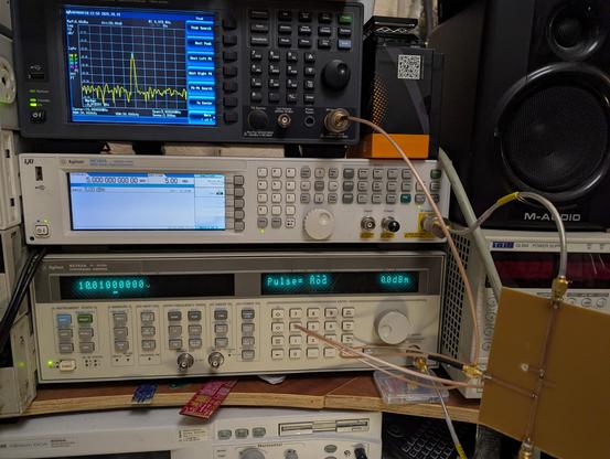
Hooked it all up to test and it kinda works!! Feeding in 10.01 GHz to RF and 5 GHz LO. RF - 2xLO mixes down to about 10 MHz shown on the spec-an.
About 25 dB conversion loss 😅 but there's probably some performance left on the table once I do any impedance matching (and, you know, maybe not use copper tape on some random copper-clad).
It turns out that tuning the stubs before adding the diodes didn't work out so well.
I tried sweeping the LO frequency while watching the amount of feed-through and it was minimised somewhere around 4.8-4.9 GHz.
I trimmed a teeny tiny bit off the stub to shift that up and the conversion loss dropped to around 18 dB 😁