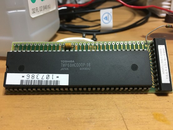
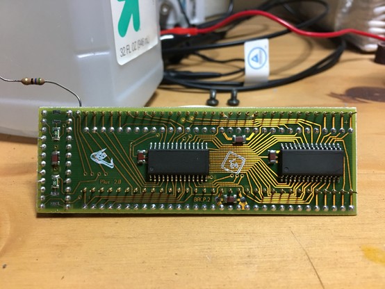
This is the Brainstorm accelerator for the Mac Plus. It plugs into a socket clipped to the top of the Plus's standard 68000 CPU. Providing its own replacement 68HC000P16 and combined with a couple of helper chips, the Brainstorm gives the Mac Plus a significant speed boost, jumping from ~8MHz to ~16Mhz. Benchmarks on LEM as proof: https://lowendmac.com/2000/mac-plus-with-16-mhz-brainstorm-upgrade-benchmarked/
Mac Plus with 16 MHz Brainstorm Upgrade Benchmarked | Low End Mac

I picked up this accelerator in a somewhat roundabout way. Months ago at the Electronics Flea Market in Saratoga, I passed a pickup truck with a couple Macs for sale. Both were facing away from me and neither were in good cosmetic shape, so I didn't think much of it at the time. Later I met a gentleman who bought a Plus from that truck and I noticed a "Brainstorm" sticker on it. I offered to trade his newly-purchased Mac in unknown condition for my known-good Plus, and we exchanged contact info.
Long story short, we swapped logic boards and indeed, he got a working Mac out of the deal. On the other hand, my Plus, though now equipped with a Brainstorm kit, no longer booted.
My Brainstorm Plus chirps out the signature "boot beep" at startup, but then during POST immediately produces a Sad Mac with error code 0101C3. The leading "01" signifies which test failed; in my case a ROM checksum failure, suggesting some kind of ROM corruption. The remaining digits are largely useless, based on the (incorrect) result of the checksum algorithm.
Armed with my rudimentary electronics skills, I cracked open my Plus to investigate. Here is where I noted a few details about how the Brainstorm works.
As I mentioned, the main board of the Brainstorm clips to a socket that straddles the original 68000 CPU. A 56ohm resistor connects the R1 pad of the Brainstorm board to the near lead of the ferrite bead FB1 on the Plus logic board.
Elsewhere on the Mac Plus logic board, the TSM-- a PAL16R4A-- is replaced by its unlabeled Brainstorm equivalent. This chip controls the frequency of DRAM refresh and its timing is coupled to that of the CPU. (I tried running my Plus with this replacement TSM but without the Brainstorm board, and while the Plus did attempt to start, its chime was razzy and the video display was unrecognizably scrambled.)
With the Brainstorm installed, each of the Plus's two ROM chips has a blue... support?... board underneath it sharing pins 1, 14, 15, and 28. I'm not sure what the purpose of these boards is-- none of their pins have any continuity, and removing them has no effect on the Sad Mac I get.
The main Brainstorm board itself consists of four ICs: a Toshiba TMP68HC000P16 CPU, a custom chip next to the 68K labeled "ASX-6" copyright Brainstorm, and on the underside two unlabeled surface-mount chips.
I beeped out the two chips on the underside and I strongly suspect they are ROMs, possibly even EEPROMs, based on the pinout. They seem to match the pinout of the 27C512 chips used by the Mac Plus ROMs, albeit in a SOP-28 package. The first troubleshooting step I'd like to try is to dump the contents of these ROMs, but alas I don't have anything that fits an SOP-28 footprint ( @tubetime ?). Likewise I'd like to dump the Plus ROMs just to verify their expected contents.
Likewise, I suspect the ASX-6 chip might be a PAL20L8 based on the pin count and how it beeps out. I drafted this incomplete schematic in KiCAD based on my findings. My maps of pins to functions might be wrong-- they're just my best guess-- but my mappings of pin numbers to pin numbers are definitely correct, as I triple-checked them. Any unmapped pins means I simply don't know their purpose; they don't connect to any other pins on the board.
Most of how the two SOP-28 chips are wired to the 68000 makes sense to me with some notable exceptions: A16 is not wired up on the Brainstorm board at all. A1-A14 are mapped according to these chips' expected word-wide use on the Plus's 16-bit data bus, but curiously, A15 is mapped to these chips' respective A15 pins, and R/W is mapped to these chips' respective A14 pins. A17 is mapped to where I expect /OE to be. What is going on? A ROM dump might shed some light here.

Finally, I'm not sure why the Brainstorm board has a pigtail resistor to the near lead of FB1 on the Plus logic board. The R1 pad on the Brainstorm board doesn't seem to connect anywhere accessible (it goes to a via that disappears under the 68000), but that pigtail seems essential for the ROMs to work. If I disconnect it, the Plus shows symptoms of no ROMs installed at all-- no boot beep, and garbage on the screen.

This accelerator certainly involved some ingenuity to develop.

@blitter based on my limited knowledge it looks like original ROM might be copied into eeprom and also patched, so they actually don't have to either provide hacked ROM on their own (aka. copyright infringement) or provide their own clean room re version. There might be an app to do that or some other way but ???.

@sobkas That's a good point. Maybe. Would need to be a mechanism somewhere to copy it while holding the 68000 in reset, or a preflight ROM that copies/patches before jumping to the "real" ROM.

Another idea I had is that given how the address lines are mapped, maybe the Brainstorm only provides a portion of the ROM, and the lines that aren't wired to the Brainstorm instead trigger the original ROMs. No copying or software patching involved.

@foone do you have any gear that can dump these?
@blitter I don't think so. I'd have to try to build something out of a breakout board and some jumpers wires
@blitter a minipro should be able to handle the dumping process, you'd just need the socket adapter. very interesting project you've got!
@tubetime I don’t suppose you already have one? That maybe you could please bring to T5 this coming Friday? 😉 At least for the DIP-28 chips which shouldn’t need an adapter.
@blitter I'll check to see if I have the right socket