
I guess I'm gonna talk a bit about the vintage computers I have accumulated over the years, what I have and haven't (yet) done to them, and maybe some extra info?
We'll see what sticks.
I guess I'm gonna talk a bit about the vintage computers I have accumulated over the years, what I have and haven't (yet) done to them, and maybe some extra info?
We'll see what sticks.
Okay, this one is for @Tijn
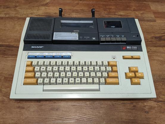
Sharp MZ-731. I think this computer was originally meant for small businesses mostly. It's graphics capabilities are essentially non-existent: It doesn't have any graphics video modes, just text modes, but surprisingly 512 characters to choose from.
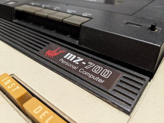
The 731 is the second highest model from the range. It featured a built-in tape recorder and plotter.
There's a 780 model, which has all that and more.
From the images in the previous post you couldn't tell it, but this computer was in an absolutely pathetic state when I got it. The ebay auction listed it as not working, but what I really got was quite something.
It looks like the entire machine was submerged in a swamp for years.
There's some sort of sludge residue and rust everywhere.
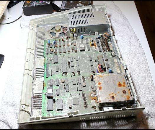
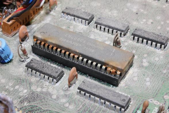
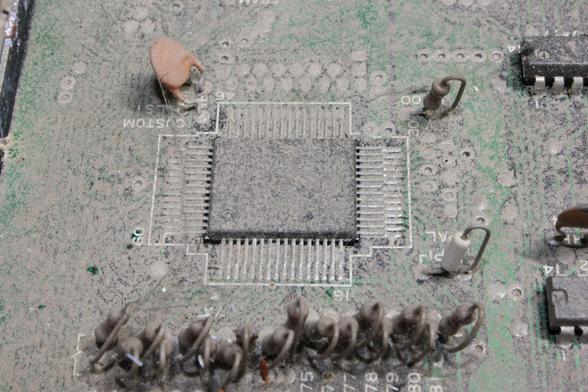
The CPU is covered entirely in rust.
As far as I can tell from the schematics, there is only a single custom chip, everything else if off-the-shelf stuff and therefore easy to replace.
But if this one logic chip is dead, then I can probably just trash the machine.
I haven't done anything but cleaning and disassembling everything. That was almost five years ago. I've bought better tools in the meantime, so I think I finally have everything I need to get working on this machine again.
I have done some research on the one custom chip.
Luckily, the entire service manual for the MZ-700 is available AND back in the day, service manuals actually deserved the name.
It explains the whole system in a lot of detail. In fact, I think a sufficiently skilled person could replicate the entire MZ-700 just with the information in the manual.
So, the chip has three major functions: CRT control, memory control, clock generation.
CRT control includes generating the PAL clocks, reading the character codes and color information from VRAM and resting the actual character pixel data from the character ROM.
Memory control does a lot of things. DRAM refresh, memory banking, DRAM row and column addressing and halting the CPU of it tries to access VRAM outside of blanking intervals.
The chip also handles peripheral IO.
But the really brilliant part is that it looks like I can test the chip mostly in isolation. Just need to give it 5V and a couple clock signals and it should run.
And thanks to the excellent description of the chip's internals, I should be able to check most if not all of its functions.
So my plan now is to attempt that. It's a first for me, but I feel I have accumulated just enough knowledge and experience to pull it off.
If it works, I know I can fix the entire machine.
So, time to clean up the workbench in the next days, desolder the IC and then run some tests.
Don't hold your breath for news, this will take at least a week, most likely longer.
If it works out, I'll rebuild the entire CPU board, replace all the 74xx logic chips, caps, resistors and other small parts and hopefully make it work again.
Wish me luck!
Here's the service manual, btw, in case anyone wants to check out just how extensive it is.
I figured it probably makes more sense desoldering the CRTC in the electronics lab at work.
I have a basic desoldering equipment at home that is fine for THT, but not for this, even with the large pin pitch.
In the lab I have access to an SMD rework station, but I've never actually done this.
So, what are your recommendations? Should I first add a bunch of fresh solder and flux to all the pins?
Put Kapton tape all over the plastic (top and bottom?) and surrounding PCB?
Alrighty, ordered a Chip Quik desoldering kit (thanks @krnlg and @zwangseinweisung!).
Apparently shipping from the UK to Germany will take between two and three weeks (oh boy). But that at least means I will actually have the time to get that pigsty of a workbench in order just in time.
It also means I get time to plan the actual test. Figure out how to connect the IC to test equipment (i.e. a bread board, a power supply and a scope), what tests to run, etc.
I don't think I'll need a lot of components to get the CRTC running, from a cursory glance at the schematic, probably just a crystal, some resistors and capacitors.
The pin pitch seems to be 1mm, too narrow to get clips onto the leads. So I think I'm gonna have to think about soldering wires onto the pins.
Oh no, it seems 17.734476MHz oscillators are kinda hard to get these days, too, and practically impossible in the package type I need.
I hope the one in the computer at the moment is okay. The package is welded shut and there shouldn't have been any relevant mechanical stress on it.
There is some rust around it on the CPU board though. Good thing is, I can desolder and test it individually long before getting started on the CRTC.
If it's broken, I'll have to get creative (or lucky).
I've removed all the rust from the CPU board (as well as I could). The board looks a lot less terrible now. Of course, there's still a lot of work ahead of me restoring the machine, but most of the rust was very superficial and hadn't yet started eating away at the copper or solder joints, yet. No idea if it ever would have - I'm no chemist and don't really understand how rust and other oxides actually spread.
But it's a lot more fun to look at the board now.
On this board, some of the vias are filled with solder. In the center of some of them, tiny specks of rust remain.
I think I'm gonna remove all the solder from them and fill them in again.
This is not very urgent though.
I measured the resistance between 5V and GND on the Sharp MZ's CPU board. It came to roughly 47Ω. I felt that's a bit low and compared some other boards I have and each of them came to a few kΩ.
Luckily I found a nice person on a retro computing forum who has a fully working similar machine (MZ-721) and they measured and got 43Ω. This checks out perfectly with mine, where some parts are missing that would lower resistance a bit further.
Looking more like it will work every day.