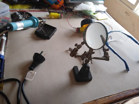
Material gathering and prepping done, time for electrical item compounding and alchemy
Okay that was messy but the cables added to the motors are working properly
Happy to see parts moving
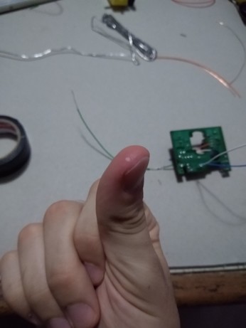

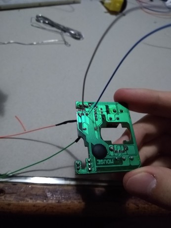
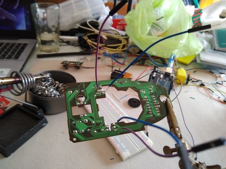
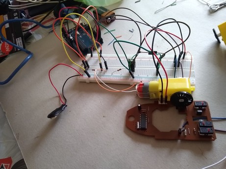
This is my other mouse board, where I didn't make the power connections personally...
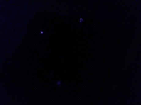
... You can see the lights a lot better, I probably made the power connections badly... In my defense those tiny cables were barely workable with
Turns out my wiring is alright and the board is getting a constant 4.9V, but I'm getting 1.7~2V on the receivers on HIGH compared to the 3.7~4V I get on the board with more visible IR lights
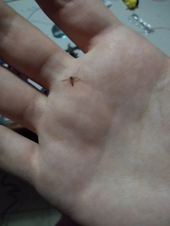
My biggest fear was that I burned the receiver when soldering the "debug" cables, but both that one and the one I didn't touch give similar, low values, that seem to correspond to the low intensity lights I see with the phone camera
1.7~2V is surely too low for the Uno to register it as a digital HIGH value, so I suppose my two alternatives now are:
- use the board I already half prepared, but use the AD to receive the values instead of the digital inputs, seeing the new thresholds myself
- ditch this one and use the other board instead, which is bigger and kinda unwieldy
... Well. The GND cable on the smaller, more worn board just got cut at the board level.
Guess I'll start work on the other board tomorrow instead of forcing this one.
I need a break either way... What I got from this first day:
- Both motors now have soldered cables and work perfectly
- The circuit to control a single motor with a MOSFET works perfectly, though of course in one direction
- I can use the board's own traces and layout to power it and solder wires to it when I need the values off its sensors
- The bigger board seems to work better, if I didn't somehow damage the smaller board myself
- soldering iron hot ouch
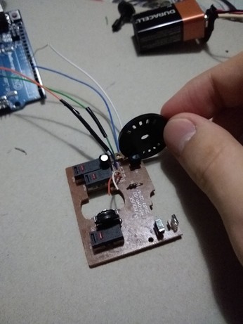
So basically each purple/blue pair are the two outputs from a dual phototransistor, kind of like a switch that gets turned on by receiving IR light instead of pressing it with your finger
There's an IR emitter on the other side, meaning that I have two "receivers" very close to each other that send me a 0 when they're blocked by something, and a 1 otherwise
Also by checking which of the two receivers changes first I can know the rotation direction, but for now it's set up to only rotate in one direction
If I have time, I can add an L298N H-bridge to fully control two wheels... I've worked with them last year
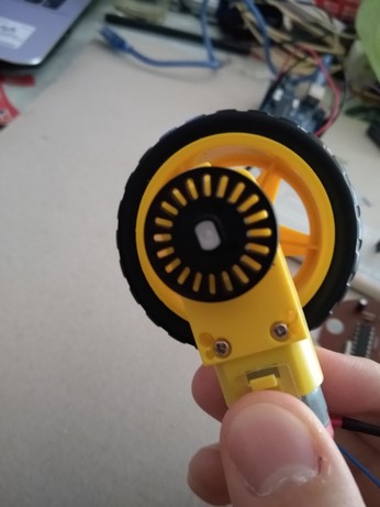
Wheel diameter is ~6.5cm, then circumference is ~33.2cm
Slotted wheel has 20 slots, meaning every transition translates into ~1.66cm of distance covered...
Hang on I can count both transitions and double the precision, I'm dumb
That's 33.2/40 = 0.83cm
I was using the formula for the fricking area instead of the circumference, I'm gonna be an engineer and I got that wrong
My brother realized that and he's laughing at me
I'll keep on tomorrow... This is the last barrier for the very least I need to turn this in
I can try one of the real time scheduling libraries, since I'm gonna have to use one to turn the project in...